Work report from the Use Case 6 “Competence Development and Competence Retaining in Value Networks” – The Arendar Learning Station
The topic of cyber security is becoming more and more important due to increasing networking and many companies, especially SMEs, are not aware of many dangers and possibilities of defense. At present, there is hardly any didactic material for training on this subject. For this reason, Arend, in cooperation with the Chair of Didactics in Technology, has set itself the goal of developing a prototype learning station and then using it for learning videos on the one hand and presenting it to manufacturers of didactic material on the other.
First Prototype
The Prototyp provides the demonstration of secure remote maintenance and secure access to data from production.
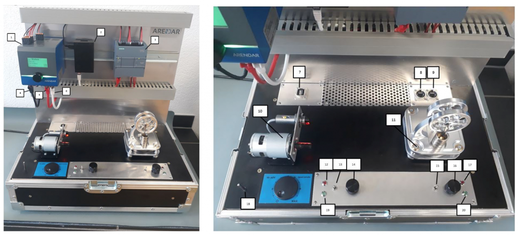
Figure 1: Real pictures of the learning station
The Learning Station contains the Edge-Gateway „Arendar“ (1), a Raspberry Pi 2 (2), and a programmable logical controller (PLC) (3). Numbers (4), (5) and (6) address the three LAN-connections of the Arendar. The Third LAN-connection is used for secure remote access and can only be physically enabled after prior proof of presence at the device. The bottom of the case houses the entire power supply, a server (Raspberry Pi 4) with WLAN, a managed switch (two separate VLAN), and an LTE stick.
For each VLAN, a LAN socket (RJ45) is routed to the outside: one for connection to a public network (8), which if available replaces connection via LTE, and one for connection to the office LAN (9). Furthermore, a USB interface (7) of the server is led to the outside. (e.g. for charging tablet or expansion functions). These three components reflect the office area of the “training company”.
Furthermore, the following components of the learning station can be seen: a 24V DC motor with light barrier for speed measurement and speed control (10), a Stirling engine with heater and thermo sensor (11), LED 1 red (12), switch 1 (13), potentiometer 1 (14), LED 2 red (15), switch 2 (16), potentiometer 2 (17), thermo sensor / transducer 1 (18), LED1 green (19) and LED 2 green (20). The switches serve as digital signal generators, the potentiometers as analog signal generators (0-10V) and the LEDs can be controlled via the digital outputs of the Arendar or via the controller. Furthermore, the temperature sensor, which measures the room temperature, serves as an analog input. Everything is embedded in a flightcase with attached metal plate.
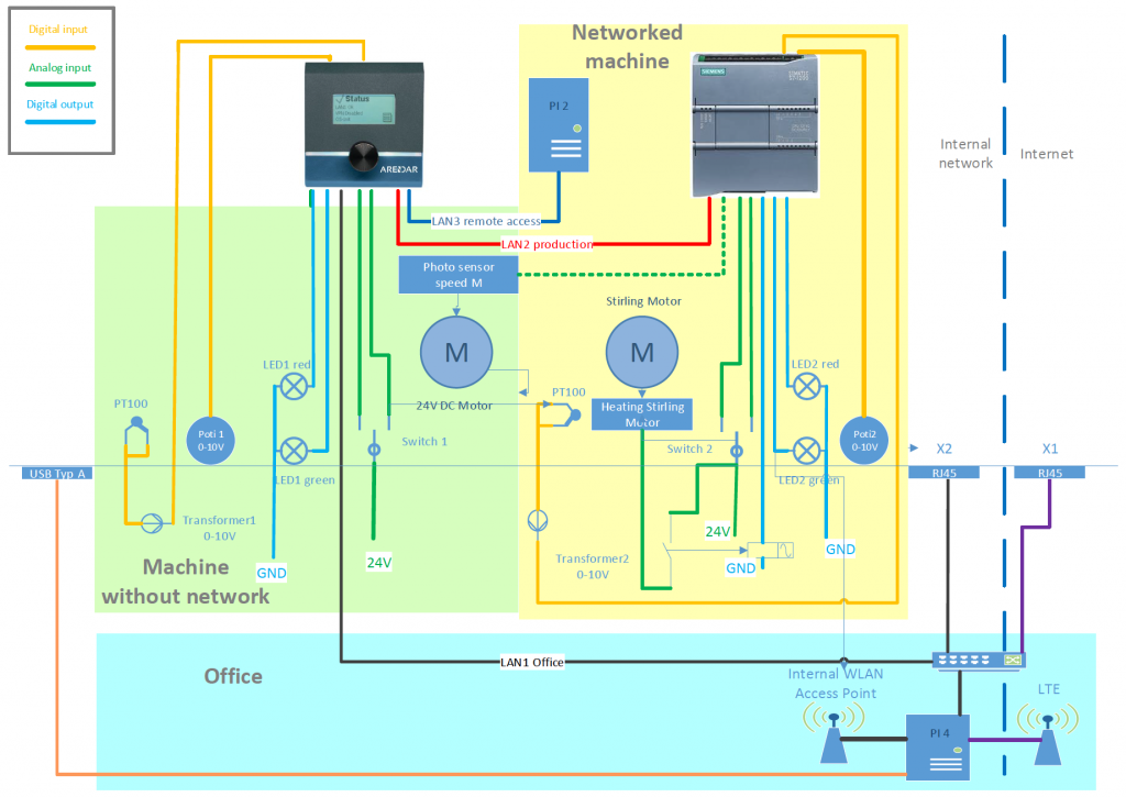
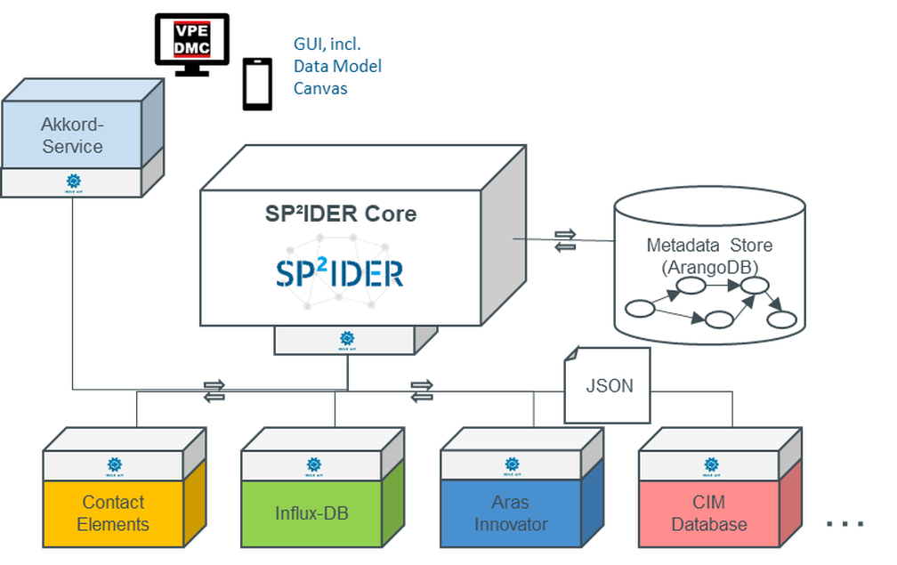
Figure 2: Schematic picture of the learning station
Fundamental Show-Cases
Several scenarios can be demonstrated with the prototype. On the one hand, the retrofitting of an older system and data acquisition by the Arendar (green area of the schematic diagram), as well as a somewhat more modern system with PLC and network connection (yellow area), where the acquisition of the machine data but also the control of the engine from the outside (office area, turquoise) is possible via the Arendar through communication with the PLC. The definition of which data may be read from the controller and which control commands may be written to the controller is configured in the Arendar and is therefore secure and limited only to released data. Secure access for remote maintenance to a system (this system is simulated here by the Raspberry Pi 2 in the upper left area of the yellow highlighted scenario) is the third level, which allows full access to a machine.
In the “Retrofitting” scenario, everything that represents sensor technology (LEDs, switch, light barrier, temperature sensor and potentiometer) is connected directly to the digital inputs/outputs and analog inputs of the Arendar’s IO card. Only data is acquired here, no function initiated externally via the Arendar takes place in the scenario. The function of the machine is not changed in any way by the acquisition of data. In terms of warranty and liability, this point is often very important. In addition, error messages or warnings can be derived from the recorded data and issued via the digital outputs of the Arendar. For example, if more than 5000 revolutions are detected, the red LED 2 is switched on as a warning.
In the scenario “Modern Plant”, all components that represent sensors are connected to the PLC and are recorded there. The Arendar is connected to the PLC via its LAN2 interface and then in turn acquires the sensor data from the controller. The heating from the Stirling engine is controlled by the controller via a relay. In this scenario, a command to turn on the engine’s heater can also be given externally via the Arendar. This can be triggered via a web interface as well as via switch 2 on the learning station.
The Raspberry Pi 2 has no actual functional task in the scenario; it can only be accessed via secure access in the “Remote Maintenance” scenario.
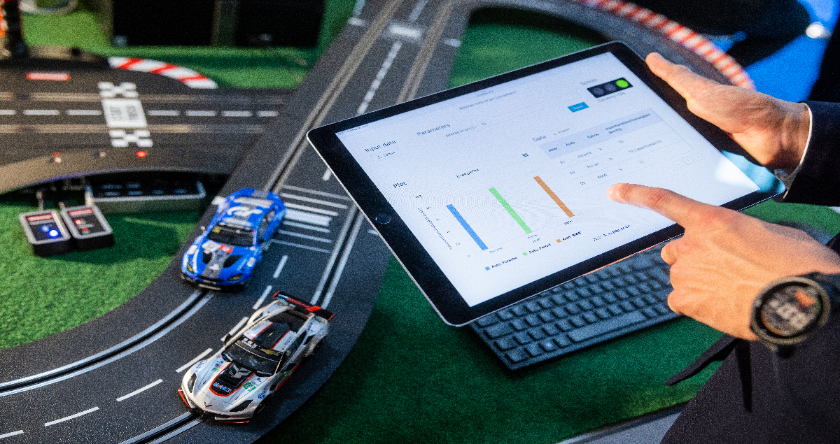
Visualization of Data
Collected data can be visualized in two ways: on the one hand via a web interface of the web server integrated in the Arendar and an external visualization via the open-source software Node-RED.
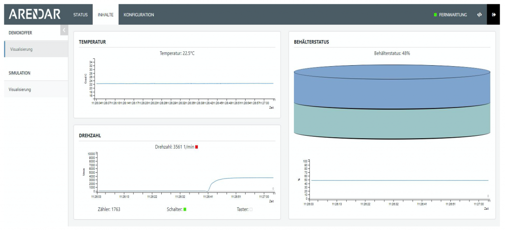
Figure 3: Webinterface of the integrated Webserver
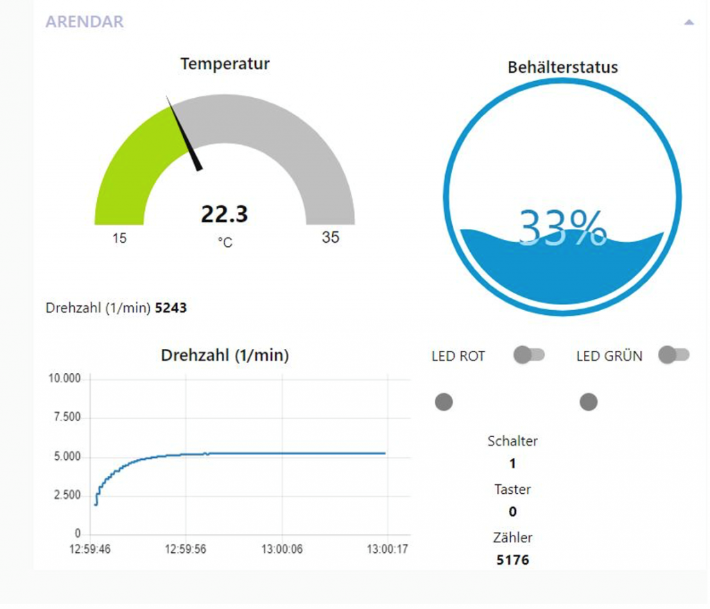
Figure 4: Visualization via Node-RED
Exercise Scenarios
The visualization can be used to construct use cases and exercise scenarios that can be mapped with the learning station. For example, the motor could represent an agitator that stirs a liquid in a container and the potentiometer would represent a level sensor in the container, i.e. changes to the level can be imported into the use case via the potentiometer. The motor speed can be monitored (stirring in an empty container without resistance leads to increased speed -> warning lamp). Or the stirring processes could be counted and after a certain number the green LED is activated (display “Done”). The liquid can be drained and refilled.
Similar use cases can be easily represented here and thus simulate practical operating cases. At the same time, it is possible to adjust parameters or generate other values in the data preprocessing by configuring the Arendar.
In the “modern machine” with PLC control, a two-point control for the heating of the Stirling engine is pre-programmed. The lower limit temperature can be set via potentiometer 2. The motor can be started via the button on the learning station or via a switch. The current state of the heating (switched on or off and heating active) is displayed via the LEDs of the learning station and in the visualization. Exercise tasks are conceivable here as well as in the configuration of the Arendar, the visualization via Node-RED and in the programming of the PLC. The security functionality of the Arendar (e.g. no unintentional manipulation of the configuration, no passing through of manipulated protocols, no unintentional access to data, …) can be built into the scenarios. In addition, the Arendar masters other protocols such as OPC UA, so that exercise tasks are also conceivable here in the area of communication (e.g., communication to Node-RED could be switched to OPC UA instead of MQTT).
A second prototype for the Chair of Didactics in Technology at the TU Kaiserslautern which is meant for training purposes is in progress.
Author and Contact Person: